A continuity tester is a vital piece of equipment to an electrical tester. It is used to establish whether an electrical circuit can be made between two points, ie. current will flow because you have a continuous circuit. This is done by de-energising the circuit that is under test, prior to connecting the test equipment.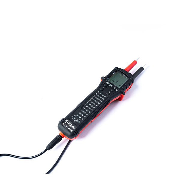
The continuity tester usually consists of a unit with two connecting leads through which a small voltage is place, and an indicator will either buzz or light up when a circuit is successfully established by the leads. The continuity test is used for simple items, such as to test switches, fuses, electrical connections, conductors and other components. As part of the continuity test a multimeter will measure the resistance established by the circuit. If low resistance is found, this means the circuit is closed and you have found electrical continuity. However, if high resistance is found, this means the circuit is open and there is little or no continuity. As a fault detection test, continuity testing can also determine if two points are connected that shouldn’t be.
It is usually recommended that a low voltage, low current device is used, particularly for situations where the testing is on high resistance circuits, or where the conductors or components are delicate or sensitive and might be damaged by excessive current.
Why do we need to carry out continuity testing?
Regulations require electrical installations to be inspected and tested before being put into service, and the continuity test forms an important part of this because it can determine:
- Whether damaged components or broken conductors exist in a circuit
- Whether soldering of the circuit is of good quality
- Whether the resistance of the circuit is too high for the current to flow
- Whether the electrical wiring is broken between the two points
- Can also check connections between pads and traces on PCBs (printed circuit boards)
How is continuity testing performed?
A continuity tester is effectively two leads connected to a battery, and when you establish a circuit by touching the leads together, you should receive a reading of zero resistance, as explained above. This zero reading is usually provided by an integral multimeter, and can be indicated by a bleep or a light coming on.
There are many benefits to the electrical tester in carrying out continuity testing, namely that tests are quick and simple and can be carried out at any time, with minimal set-up and using very few resources. The tests are very reliable and are quicker than having to run many repetitive standardised tests. The continuity test can also test for shorts in the circuit as well as continuity.
You can speak to our expert sales team at TIS on the benefits and practicality of our range of continuity testers, so get in touch today!