It is widely accepted that the multi-function tester is the most popular instrument for the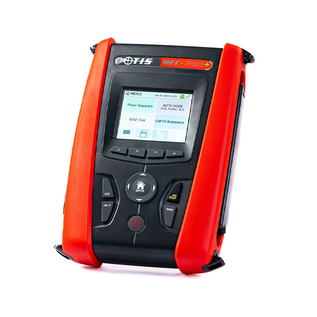 electrical tester. It is a flexible instrument that can be adapted for many different purposes, and saves the testing engineer a lot of time and inconvenience in swapping between different tools. However, it is important that the user knows how to use the instrument for the procedure they are performing, and they should check the user manual for the specifications for each test. Fundamentally they should also be trained and qualified to carry out the tests and should carry out risk assessments so that each test is safe and compliant.
In order to ensure you understand the test results you are generating, it is important to build a knowledge of what each test represents and what its purpose is. The overall purpose of a multi-function tester is to check the safety of circuits in commercial and industrial settings, and to ensure the wiring meets safety standards and industry regulations. However, once we have the results, here is a brief overview of what each test is telling us.
Interpreting multi-function tester results
There are seven very common uses for a multi-function tester:
Continuity testing – this is for checking whether a circuit is open or closed and therefore if there is current flow in the circuit. If there are broken conductors, a damaged component or excessive resistance, current won’t flow in a circuit and it is broken. So the result of a continuity test is a simple yes or no.
Earth loop impedance testing – if there is a fault in an electrical circuit, the earth loop impedance test should be conducted to ensure the fault current is sufficiently strong. It should be strong enough to set off the circuit protection in place, which would normally be a fuse or circuit breaker. So is there enough current flow to operate the circuit protection within a predetermined time? This is to represent the chances of the circuit shutting off before it overheats or catches fire.
Insulation resistance testing – this test measures the total resistance between two points that are separated by electrical insulation. In other words, this is testing the effectiveness of insulation, usually around wiring or cables. The test is determining how well the insulation will resist the flow of current. Resistance is measured in ohms and a high result suggests the insulation is letting very little current escape through it, while a low result suggests current is leaking through it.
Residual Circuit Device testing – this is the process of checking whether an RCD in a circuit is operating correctly, ie. shutting down the circuit when needed. This helps to identify when an incorrect RCD has been installed. The correct functioning of an RCD will cut power to an appliance or circuit, and if not there may be a fault with the appliance or circuit, or the RCD is the incorrect type or is not working properly.
PAT Testing – PAT testing is the process of checking electrical appliances for safety. The tests involve a visual inspection of the appliance and associated cabling, but also involves checking the cables and appliances to test their integrity. The results are a simple pass or fail, usually accompanied by actual test readings.
EV chargepoint testing – EVSE includes the charger and associated cabling and connections, and EVSE testing involves testing to ensure the system has been installed correctly and continues to perform correctly. Using an adaptor attached to the multi-function tester to mimic the presence of an electric vehicle, EVSE testing tests for correct wiring, safe voltage and current flow, whether RCDs are functioning correctly if there is a fault, whether the system is earthed, that insulation of the charging cable is sufficient & some adaptors can even simulate vehicle faults to make sure that the charger cuts off the power in such events.
Short circuit current tests – this ensures the safety of users when equipment is stressed by very high currents, and includes tests of components, panels, fuses and connections. The test determines the branch parameters of the equivalent circuit of a transformer. The test is conducted on the high voltage side of a transformer where the low voltage side has been short-circuited.
Contact Test Instrument Solutions for how to use a multi-function tester
At Test Instrument Solutions we can supply you with the award-winning multi-function tester the MFT-Pro. This instrument can carry out the series of tests outlined above with high accuracy and reliability. If you contact our team at Test Instrument Solutions we can advise you on the suitability of the MFT-Pro and how it can help you achieve your electrical testing goals.
Video Demonstration
Find out more about the MFT-Pro (multi-function tester) product in the below video:
Please note that this section is for information purposes only. Anyone using equipment referred to in this section must be suitably qualified and/or experienced within the respective field. If in doubt before use, please consult a qualified electrician or engineer & thoroughly read all instruction booklets.